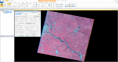
This lab contained an overview of five different remote sensing techniques. First, image subsetting is used to selected a smaller area of study from the original image. Second, optimization of image resolution was achieved by increased ability of visual interpretation. Third, section radiometric techniques were used for increased image spectral and radiometric data. Fourth, Google earth is linked with the original image to increase image interpret through the additional satellite imagery. Lastly, in the fifth section resampling methods were used.
Methods
Part 1: Subsetting Images Inquire Box: Here, I began with an original image. From here I used the Raster tools, to create a Inquire Box. This allowed me to selected a smaller area of the original image I was interested in studying.
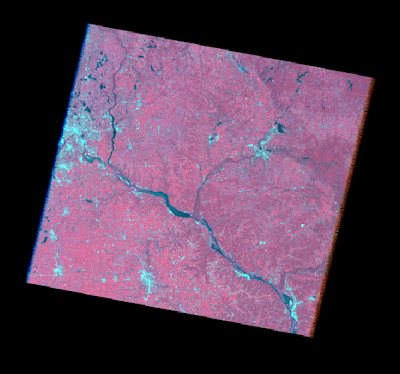 |
| Original Image |
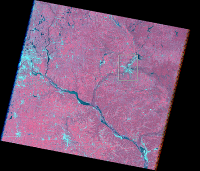 |
| Image with Inquire Box |
Once I selected my chosen area of Eau Claire County, next under the Raster tab, I chose Subset and Chip, then Subset Image to create my new output.
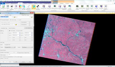 |
| Tab open to create Subset image |
In the new pop up, under the Output file, I clicked on the folder I wanted the new image to be saved to and named the file. Next, I clicked on the button From the Inquire Box, which enters the new Inquire Box coordinates. Now, I completed the model run which generated my new subset output.
Shape File: Here, I opened an original photo, then and a shape file which laid on top the original.
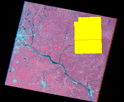 |
| Original Image with Shapefile overlaid |
I selected these boxes, the clicked the paste from selected objects button to create an outline of previously selected area. To create the aoi file, I saved to a new file under AOI layer as. From here I clicked on Subset and Chip to create another subset output image as before. This time, I clicked the AOI button to select my file of my area of interest. From here, I completed the model run and generated another output.
Part 2: Image FusionHere, I began with an original image, and a panchromatic image in two separate viewers.
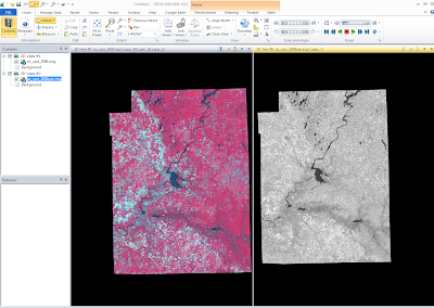 |
| Original Image (left), Panchromatic (right) |
Under the Raster tool bar, I clicked on Pan Sharpen then Resolution Merge. Here for high resolution I used the panchromatic image, and for the multispectral I used the original input reflective image. Then I selected an output folder then created a name for the new output image. I also specified I was using the multiplicative Method, and the nearest neighbor Resampling Technique.
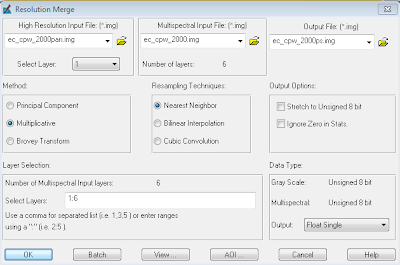 |
| Resolution Merge Window |
From here, I completed the model run and created the output image. From here, I was able to compared the new pan-sharpened image to the original input reflective image.
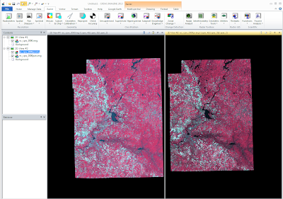 |
| original input reflective image (left) new pan-sharpened image (right) |
Part 3: Radiometric enhancement techniquesFirst I opened up an original image. From here I clicked on the Raster tool bar, then on Radiometric to Haze Reduction.
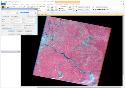 |
| Screen Capture with Haze Reduction Window |
After I selected the file I wanted under my input file, I selected with Output folder I wanted the output image to be saved in. I also created a file name. From here I completed the model run which generated the new haze reduction output file. I was then able to compare the output to the original image.
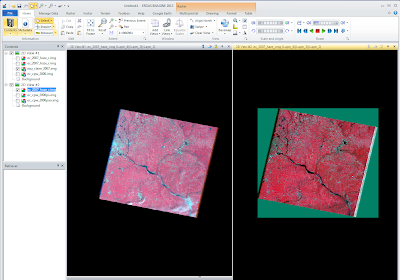 |
| Original (left), Haze Reduction (right) |
Part Four: Linking Google Earth
Here, first I opened up an image, then clicked on the Google Earth tool bar. From here I clicked Connect to Google Earth.
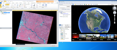 |
| Original Image (left), Google Earth Window (right) |
One this new window was loaded, I then selected Match GE to View.
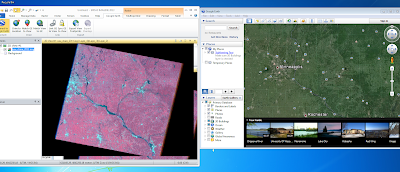 |
| Original Image (left), Google Earth Window (right) |
From here, I synchronized the two views by clicking Sync GE to View. Now when I zoom in to the left original picture, the Google Image with zoom in to same location with the same magnification.


