In this lab, image processing was practiced through the use of geometric correction. Two type of two types of geometric correction was used, called Image-to-Map Rectification, and Image-to-Image Registration.
Methods
Part 1: Image-to-Map Rectification
First, under the Multispectral tab, Control Points was selected. From there, Polynomial was selected within the window.
From here, the Multipoint Geometric Correction window popped up, and all default settings were accepted. Next, the reference image was selected. After this the Reference Map window pops up, and okay was selected. Following this, the Polynomial Model Properties window appears and all default settings are accepted once Close is selected.
Now, in the Multipoint Geometric Correction window, all points into the lowest box were deleted. After both the reference image and imput image were "fit to screen", new GCP points were added. Specifically, 4 points were added to both images. After specific adjustments were completed by zooming , the RMS error and the Total RMS Error were less than 2.0.
Part 2: Image to image registration
Two images were opened in the different viewers. One had significant image distortion. Again, the Multispectral tab was selected, following the Control Points button. For the following windows, the default settings were accepted. In the Polynomial Model Properties box, the polynomial order was changed to 3. From here, 12 GCP's were added simultaneously to the input image and the reference image.
After all points had an RMS error less than 1, and the Total RMS error was less than 1, the Display Resample Image Dialog button was selected. Here, the output image was named, and the settings in the Method box were changed to Bilinear Interpolation. From here, Okay was selected and the output image was generated.
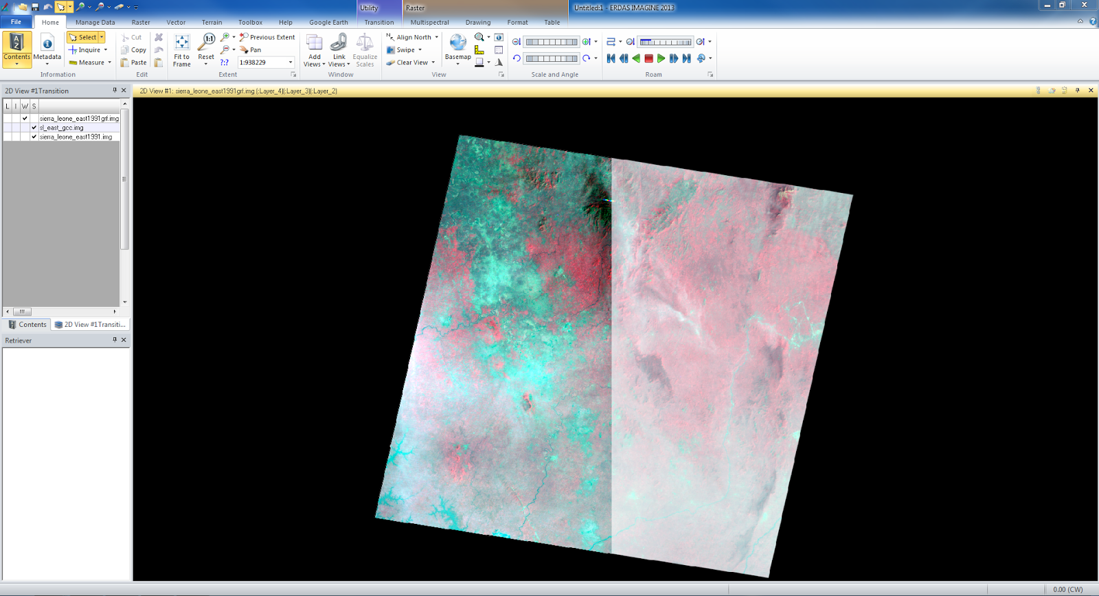
Next, the output image was overlapped on the reference image. The distortion between the images appears to be almost inexistent. This appears below.
 |
| The reference image appears on the left, and the output image appears on the right. |


No comments:
Post a Comment